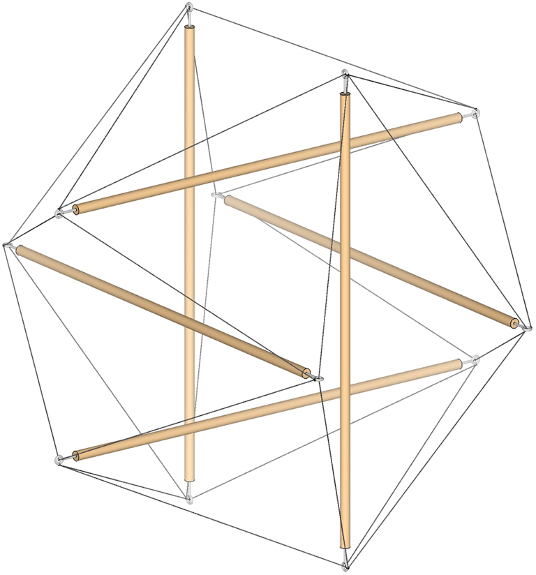
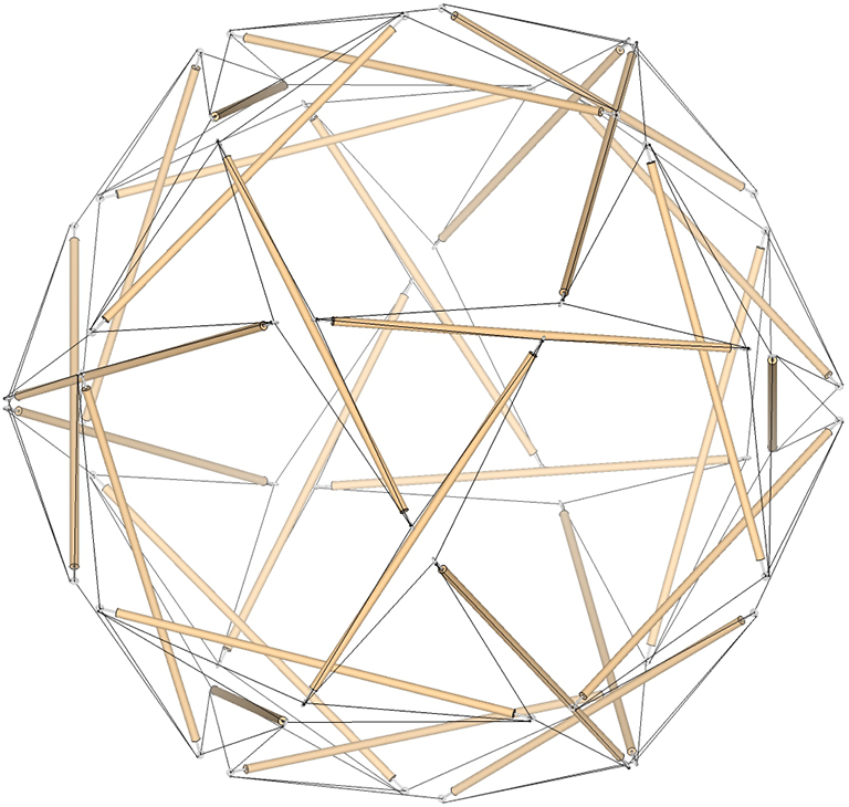
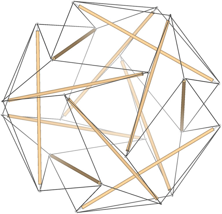
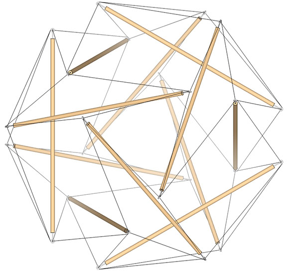
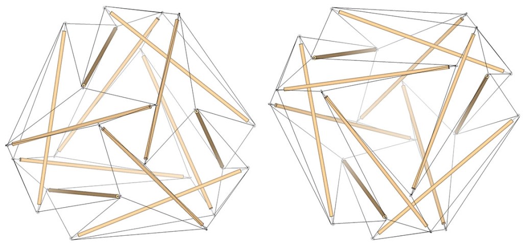
The 6-strut tensegrity sphere is the spherical, or tensor equilibrium phase of the tensegrity tetrahedron and its dual, which is the same tensegrity tetrahedron but with a 90° rotation and with vertices oriented counter-clockwise to the other.
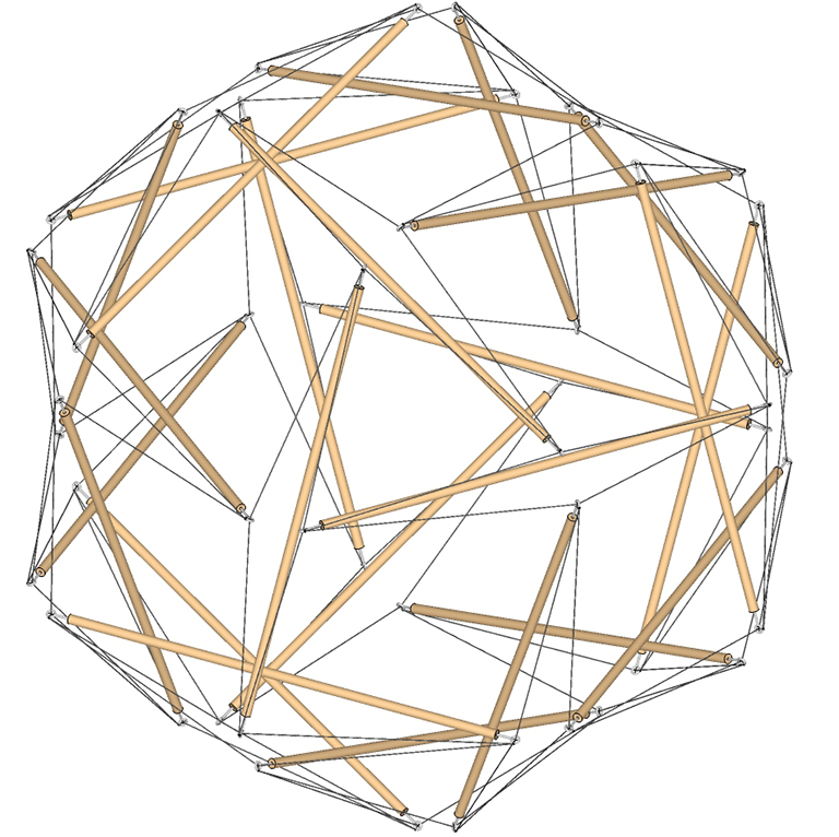
The 6-strut tensegrity sphere.
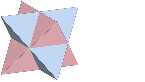
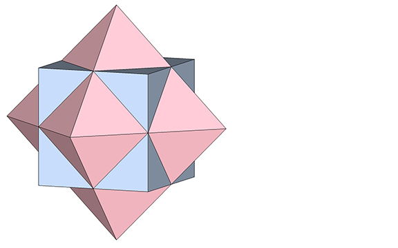
The dual of the regular tetrahedron is conventionally described as the same tetrahedron. Its dual is here described as the negative of the other.
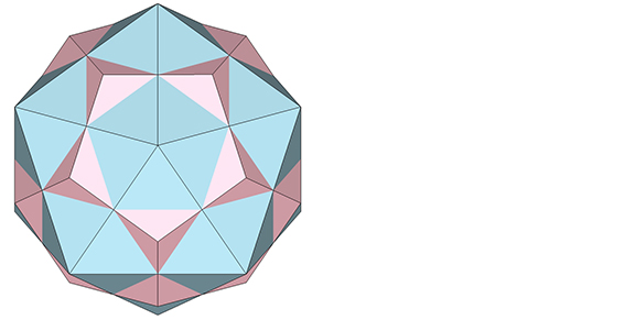
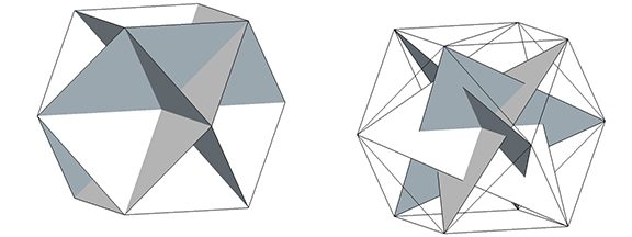
The positive tetrahedron (blue) and its dual, the negative tetrahedron (pink). Note that the vertices in one are the faces in the other, and vice versa.
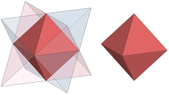
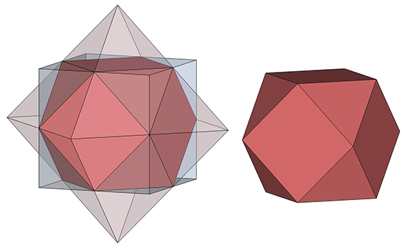
Rectification of either (or the intersection of both) produces the regular octahedron.
Rectification of either (or the intersection of both) a positive and negative tetrahedron (left) produces the octahedron. Note that the edges of the two tetrahedra cross at the vertices of the octahedron.
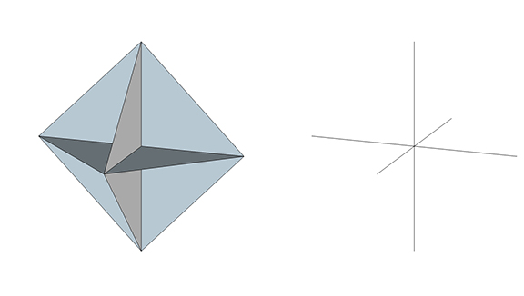
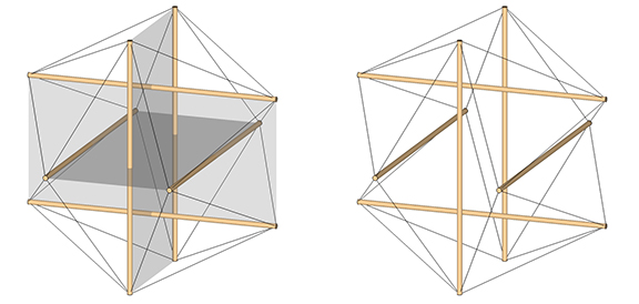
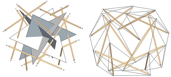
The 12 edges of the octahedron describe three intersecting squares. Connecting alternate vertices of these squares describes three intersecting lines aligned with the distribution of the struts in the 6-strut tensegrity sphere. For consistency, the three lines are here described as three 2-sided polygons, all sharing a common center and each intersecting the other at 90°.
The 12 edges of the octahedron describe three intersecting squares (left). Connecting alternate vertices describes three intersecting lines, or what we’re calling 2-sided polygons (right).
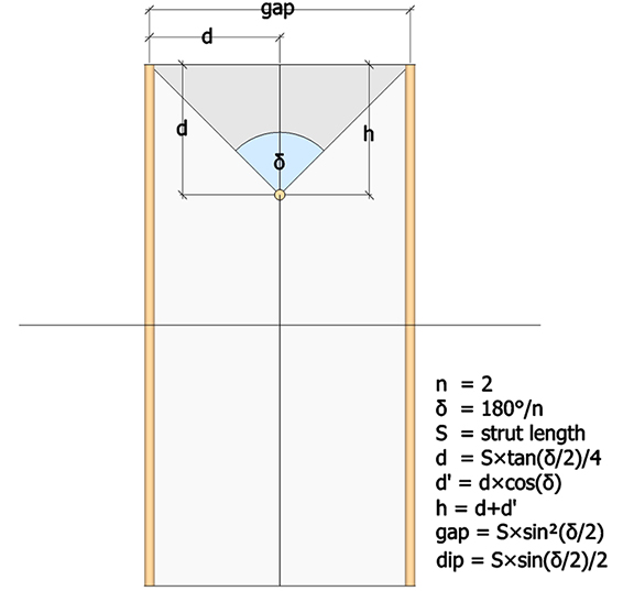
Each of the three intersecting lines (or 2-sided polygons) of the 6-strut tensegrity sphere consists of two struts and the triangular cross section of the valley formed by the tendons connecting each strut-pair to its dangler. The dimensions of this triangular cross-section are illustrated below.
n (number of sides of the polygon) = 2
δ = 180°/n = 90°
S = strut length
d (vertical distance from polygon’s edge to strut) = S×tan(δ/2)/4
d’ (height of the triangle formed by the strut ends and the polygon’s vertex) = d×cos(δ) = 0
h (height of the triangle formed by the strut ends and the midpoint of their dangler strut) = (d+d’) = (d+0) = d.
gap (distance between strut ends) = S×sin²(δ/2)/2
dip (distance from strut end to midpoint of dangler strut) = S×sin(δ/2)/2
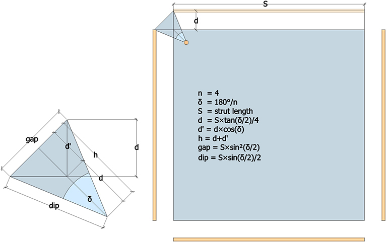
Dimensions of the cross section of the tension valley formed by the four tendons of a strut pair and their dangler in the 6-strut tensegrity sphere.
In its spherical, or equilibrium phase, the dimensions of the cross section of the tension valley created by the tendons reach their maximum. In the polyhedral phases described below, δ approaches to 0°, and both the gap and dip go to zero (0).
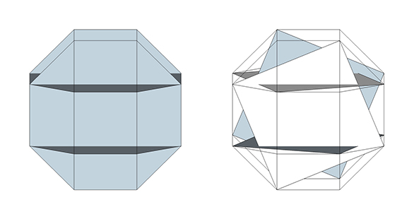
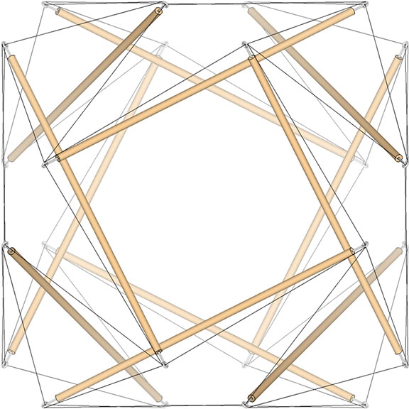
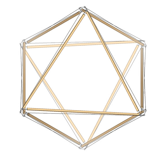
In its spherical, or equilibrium phase, the struts are at their maximum distance from the unit edges of the three intersecting 2-sided polygons (left) of the 6-strut tensegrity sphere (right). For clarity, the 2-sided polygons are shown as transparent rectangles.
Transformation of the 6-Strut Tensegrity Sphere into Positive (or Clockwise) and Negative (or Counter-Clockwise) Tetrahedron.
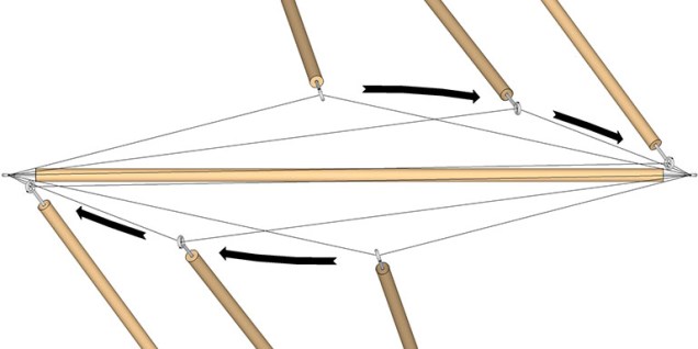
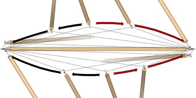
From the spherical phase, the 6-strut tensegrity sphere is reduced to the tensegrity tetrahedron by sliding the strut ends along the tendon toward opposing ends of their dangler, as illustrated below.
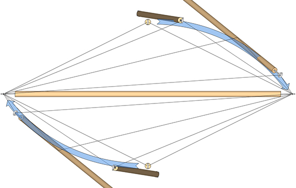
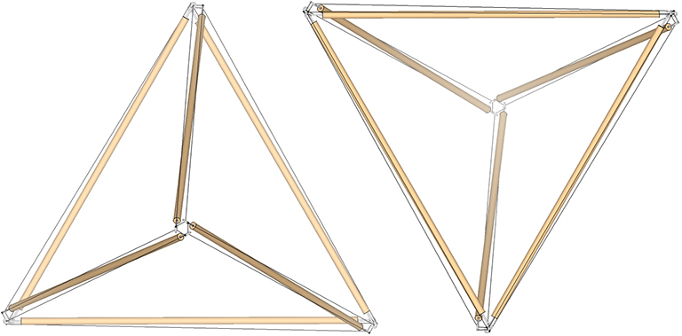
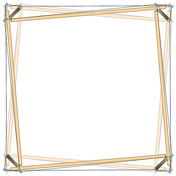
Moving the struts in one direction results in the positive tensegrity tetrahedron…
In the transformation from 6-strut tensegrity sphere to tensegrity tetrahedron, the strut ends move along the tendon to opposing ends of their dangler.
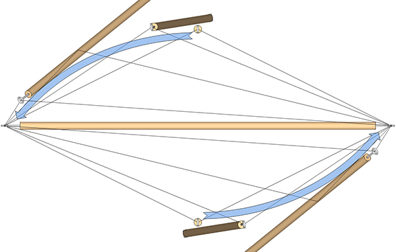
…and moving the struts in the opposite direction results in the negative tensegrity tetrahedron.
In the transformation to the negative tensegrity tetrahedron, the strut ends swap positions at opposing ends of their dangler
The surface of the 6-strut tensegrity sphere describes eight triangular tendon-loops. In the transition to the tetrahedron, four transform into the tetrahedron’s four faces, and the other four transform into the tetrahedrons four vertices. Their roles are swapped in the transformation to the negative tetrahedron.
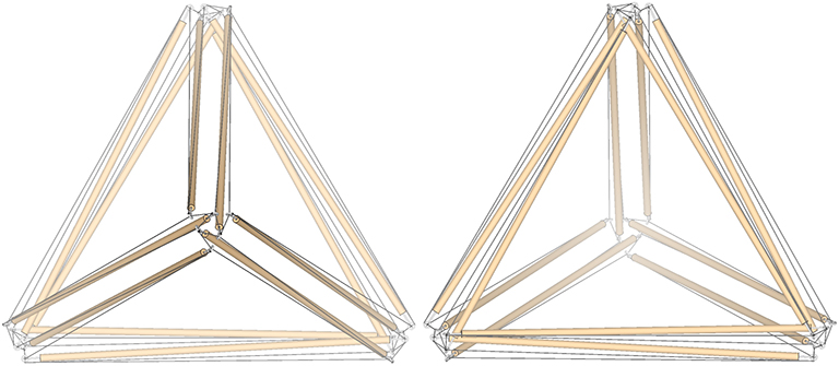
The oscillation of the 6-strut tensegrity sphere produces both the clockwise (or positive) tensegrity tetrahedron (right), and the counter-clockwise (or negative) tetrahedron (left).
The oscillation from the tensor equilibrium (spherical) phase, to the extremes of the two tetrahedron phases, may be stopped at any point and the model will hold its shape. As long as the elasticity and tautness of the tendons is maintained, the models do not show a preference for one state over another.
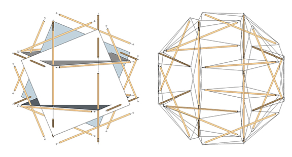
6-strut tensegrity sphere oscillates smoothly from its spherical phase, between the extreme of its polyhedron phases (the positive and negative tensegrity tetrahedron) all the time holding its shape and showing no preference for one phase over another. .
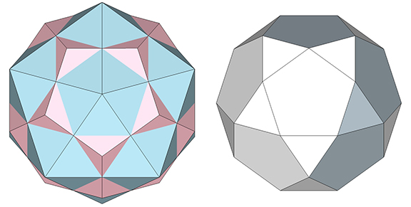
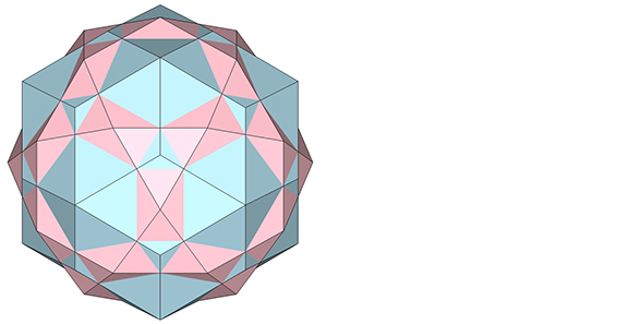
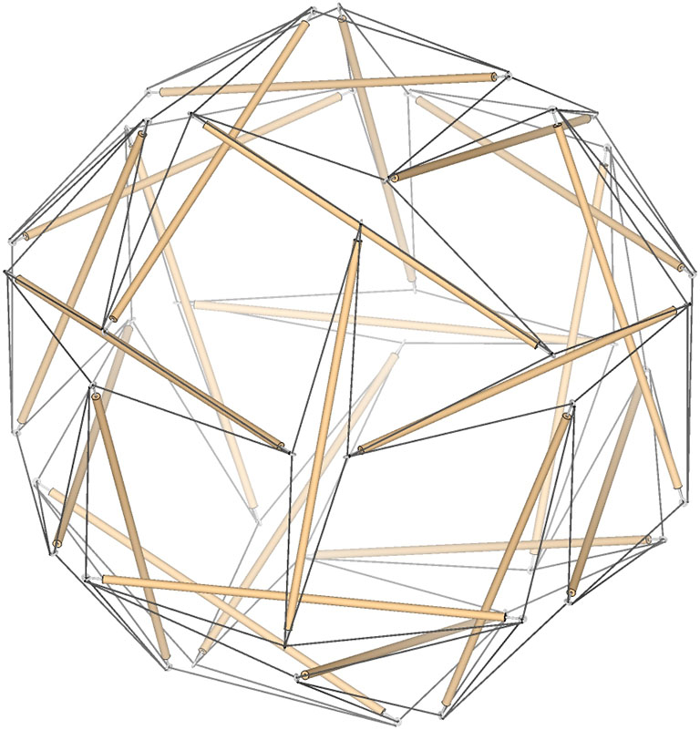
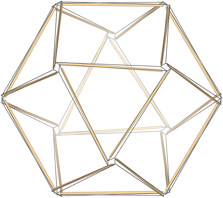
The 30-strut tensegrity sphere is the spherical, or tensor equilibrium phase of the regular icosahedron and its dual, the pentagonal dodecahedron.
30-Strut Tensegrity Sphere
The pentagonal dodecahedron is the dual of the icosahedron.
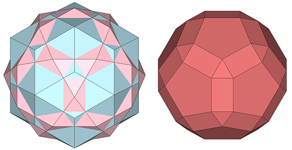
The regular icosahedron (blue) and its dual, the pentagonal dodecahedron (pink). Note that the vertices in one are the faces in the other, and vice versa.
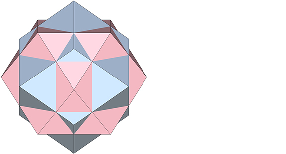
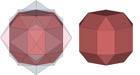
Rectification of either (or the intersection of both) produces the icosidodecahedron.
Rectification of either the regular icosahedron or pentagonal dodecahedron (left), or the intersection of both, produces the icosidodecahedron (right). Note that the edges of the regular icosahedron and the pentagonal dodecahedron cross at the vertices of the icosidodecahedron.
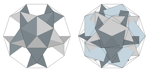
The 60 edges of a icosidodecahedron consist of six intersecting decagons (10-sided polygons). Connecting alternate vertices of the six decagons produces six pentagons whose edges align with the distribution of the struts in the 30-strut tensegrity sphere.
The 60 edges of the icosidodecahedron describe six intersecting decagons (left). Connecting alternate vertices describes six intersecting pentagons (right) whose edges align with the distribution of struts in the 30-strut tensegrity sphere.
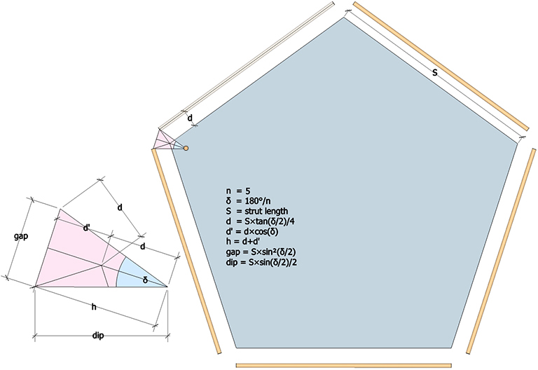
Each of the six intersecting pentagons of the 30-strut tensegrity sphere consists of five struts and the triangular cross section of the valley formed by the tendons connecting each strut-pair to its dangler. The dimensions of this triangular cross-section are illustrated below.
n (number of sides of the polygon) = 5
δ = 180°/n = 36°
S = strut length
d (vertical distance from polygon’s edge to strut) = S×tan(δ/2)/4
d’ (height of the triangle formed by the strut ends and the polygon’s vertex) = d×cos(δ)
h (height of the triangle formed by the strut ends and the midpoint of their dangler strut) = d+d’
gap (distance between strut ends) = S×sin²(δ/2)/2
dip (distance from strut end to midpoint of dangler strut) = S×sin(δ/2)/2
Dimensions of the cross section of the tension valley formed by the four tendons of a strut pair and their dangler in the 30-strut tensegrity sphere.
In its spherical, or equilibrium phase, the dimensions of the cross section of the tension valley created by the tendons reach their maximum. In its polyhedral phases (described below), δ approaches 0°, and both the gap and dip approach zero (0).
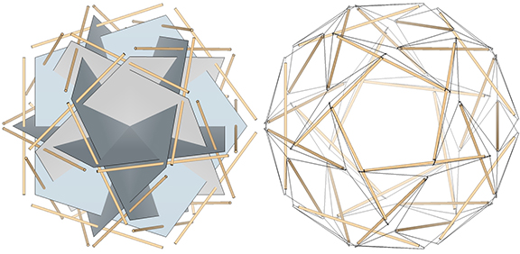
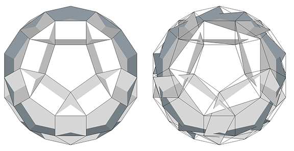
In its spherical, or equilibrium phase, the struts are at their maximum distance from the unit edges of the six intersecting pentagons (left) of the 30-strut tensegrity sphere (right)
Transformation of the 30-Strut Tensegrity Sphere to the Tensegrity Icosahedron and the Tensegrity Pentagonal Dodecahedron
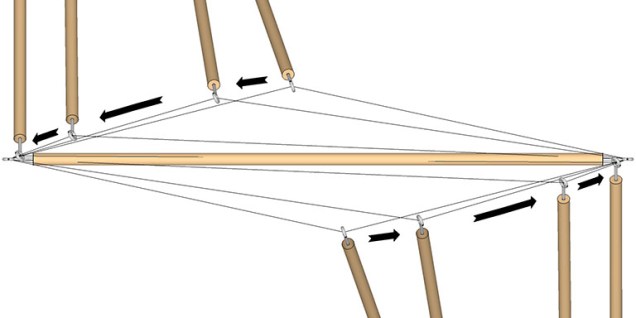
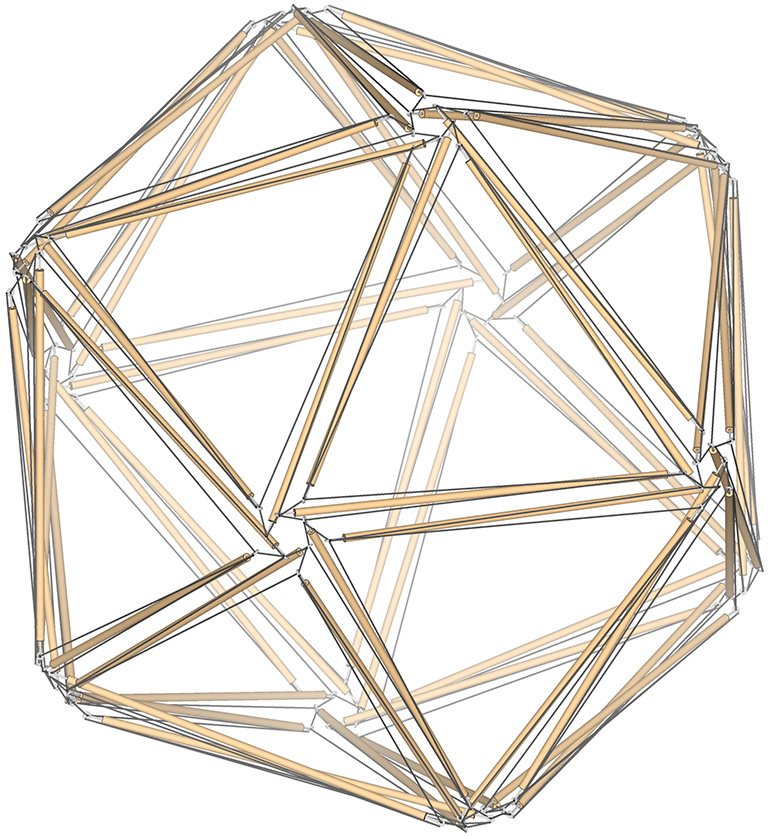
From the spherical phase, the 30-strut tensegrity sphere is reduced to the tensegrity icosahedron by moving each strut along the short tendon toward the end of its dangler, as illustrated below.
In the transformation from 30-strut tensegrity sphere to tensegrity icosahedron, each strut end moves along the short tendon to the end of its dangler.
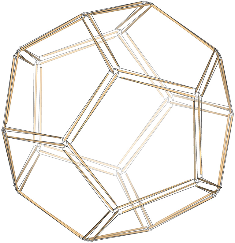
The sphere is reduced to the tensegrity pentagonal dodecahedron by moving each strut along the long tendon toward the end of its dangler, as illustrated below.
In the transformation from 30-strut tensegrity sphere to tensegrity pentagonal dodecahedron, each strut end moves along the long tendon to the end of its dangler.
The surface of the 30-strut tensegrity sphere describes twenty triangular tendon-loops, and twelve pentagonal tendon-loops. In the transition to the icosahedron, the twenty triangular tendon loops transform into the icosahedron’s twenty faces, and the twelve pentagonal loops transform into its twelve vertices. In the transition to the pentagonal dodecahedron, the roles are reversed: the twenty triangular loops become its vertices, and the twelve pentagonal loops become its faces.
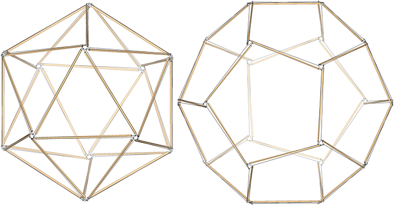
30-strut tensegrity icosahedron (left) and 30-strut tensegrity pentagonal dodecahedron (right)
The oscillation from the tensor equilibrium (spherical) phase, to the extremes of the icosahedron and pentagonal dodecahedron phases, may be stopped at any point and the model will hold its shape. As long as the elasticity and tautness of the tendons is maintained, the models do not show a preference for one state over another.
The 30-strut tensegrity oscillates smoothly from its spherical phase, between the extremes of its polyhedron phases, all the time holding its shape and showing no preference for one phase over another.
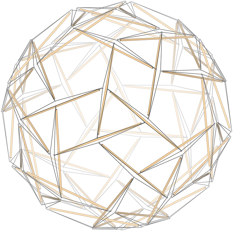
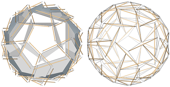
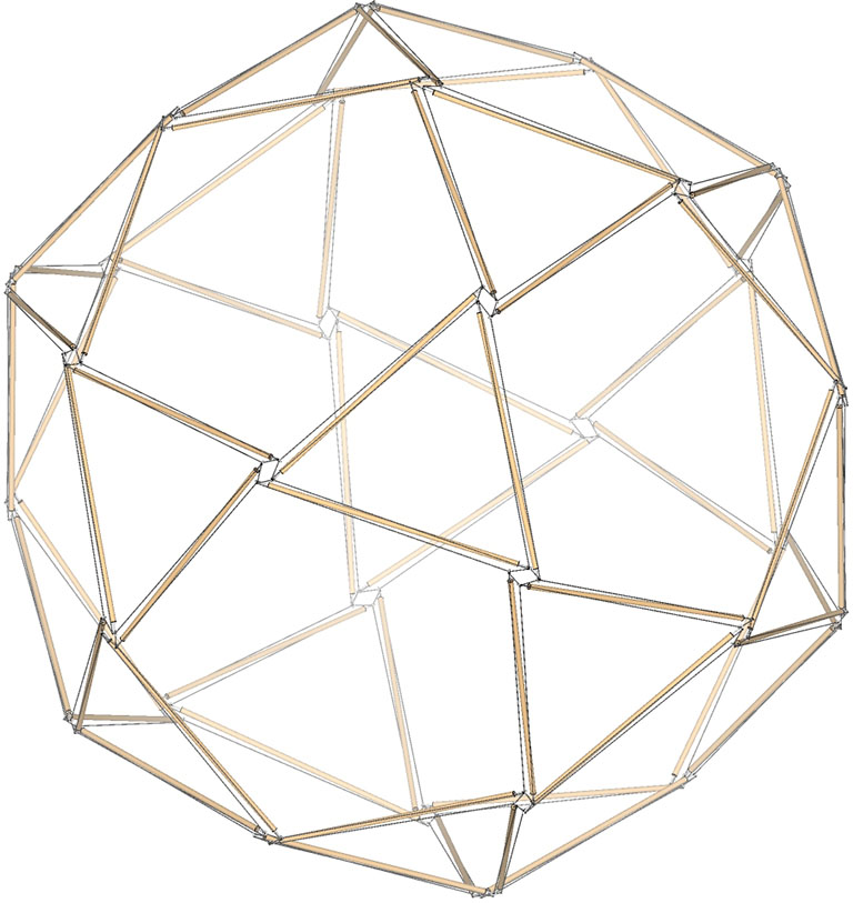
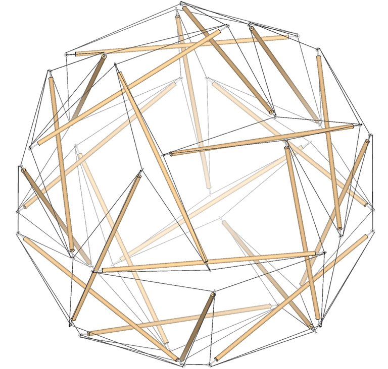
The 60-strut tensegrity sphere is the spherical, or tensor equilibrium phase of the rhombic triacontahedron and its dual, the icosidodecahedron. It also reduces to the double-edge icosahedron and its dual, the double-edge pentagonal dodecahedron.
The 60-strut tensegrity sphere
The rhombic triacontahedron is the dual of the icosidodecahedron.
The rhombic triacontahedron (blue) and its dual, the icosidodecahedron (pink). Note that the vertices in one are the faces in the other, and vice versa.
Rectification of either (or the intersection of both) produces a non-uniform rhombicosidodecahedron.
Rectification of either the rhombic triacontahedron or the icosidodecahedron (left), or the intersection of both, produces the rhombicosadodecahedron (right). Note that the edges of the rhombic triacontahedron and icosidodecahedron cross at the vertices of the rhombicosidodecahedron.
The 120 edges of a rhombicosadodecahedron consist of twelve intersecting decagons (10-sided polygons). If we make the twelve decagons uniform and connect alternate vertices, we produce twelve pentagons whose edges align with the distribution of the struts in the 60-strut tensegrity sphere.
The 120 edges of the uniform rhombicosidodecahedron describe twelve intersecting decagons (left). Connecting alternate vertices describes twelve intersecting pentagons (right) whose edges align with the distribution of struts in the 60-strut tensegrity sphere.
Each of the twelve intersecting pentagons of the 60-strut tensegrity sphere consists of five struts and the triangular cross section of the valley formed by the tendons connecting each strut-pair to its dangler. The dimensions of this triangular cross-section are illustrated below.
n (number of sides of the polygon) = 5
δ = 180°/n = 36°
S = strut length
d (vertical distance from polygon’s edge to strut) = S×tan(δ/2)/4
d’ (height of the triangle formed by the strut ends and the polygon’s vertex) = d×cos(δ)
h (height of the triangle formed by the strut ends and the midpoint of their dangler strut) = d+d’
gap (distance between strut ends) = S×sin²(δ/2)/2
dip (distance from strut end to midpoint of dangler strut) = S×sin(δ/2)/2
Dimensions of the cross section of the tension valley formed by the four tendons of a strut pair and their dangler in the 60-strut tensegrity sphere.
In its spherical, or equilibrium phase, the dimensions of the cross section of the tension valley created by the tendons reach their maximum. In its polyhedral phases (described below), δ approaches to 0°, and both the gap and dip go to zero (0).
In its spherical, or equilibrium phase, the struts are at their maximum distance from the unit edges of the twelve intersecting pentagons (left) of the 60-strut tensegrity sphere (right)
Transformation of the 60-Strut Tensegrity Sphere to the Tensegrity Rhombic Triacontahedron
From the spherical phase, the 60-strut tensegrity sphere is reduced to the tensegrity rhombic triacontahedron by moving each strut along the short tendon toward the end of its dangler, as illustrated below.
In the transformation from the 60-strut tensegrity sphere to the tensegrity rhombic triacontahedron, each strut moves along the short tendon to the end of its dangler
The surface of the 60-strut tensegrity sphere describes twenty triangular tendon-loops, twelve pentagonal tendon-loops, and thirty rhombic loops.
In the transition to the rhombic triacontahedron, the thirty rhombic tendon loops transform into the rhombic triacontahedron’s thirty rhombic faces, the twelve pentagonal loops and twenty triangular loops transform into its 5- and 3-vector vertices respectively.
Tensegrity Rhombic Triacontahedron
60-strut tensegrity transforming from its spherical phase to the rhombic triacontahedron.
Transformation of the 60-Strut Tensegrity Sphere to the Tensegrity Icosidodecahedron
From its spherical phase, the 60-strut tensegrity sphere is reduced to the tensegrity icosidodecahedron by moving each strut along the long tendon toward the end of its dangler, as illustrated below.
In the transformation from 60-strut tensegrity sphere to the tensegrity icosidodecahedron, each strut end moves along the long tendon to the end of its dangler.
In the transition to the icosidodecahedron, the thirty rhombic tendon loops transform into the icosidodecahedron’s thirty vertices, while the the twelve pentagonal and twenty triangular loops transform into its twelve pentagonal and twenty triangular faces.
60-strut tensegrity icosidodecahedron
60-strut tensegrity transforming from its spherical phase to the icosidodecahedron.
Transformation of the 60-Strut Tensegrity Sphere to Double-Edge Tensegrity Pentagonal Dodecahedron
From its spherical phase, the 60-strut tensegrity can be transformed into a double-edge pentagonal dodecahedron or a double-edge icosahedron by moving the strut pairs together to either the left or right end of their danglers. That is, one strut moves along the short tendon, while the other moves along the long tendon toward the same end of their dangler.
In the transformation from 60-strut tensegrity sphere to the double-edge tensegrity pentagonal dodecahedron, each strut pair moves in the same direction to one end or the other of their dangler.
In the illustration below, the 60-strut tensegrity sphere’s twenty triangular loops have contracted to form the vertices of the double-edge pentagonal dodecahedron, while the twelve pentagonal tendon loops have expanded into its twelve pentagonal faces, and the thirty rhombic tendon loops have transformed into its thirty edges.
60-strut tensegrity transforming between its spherical phase and the double-edge pentagonal dodecahedron.
Transformation of the 60-Strut Tensegrity Sphere to the Double-Edge Tensegrity Icosahedron
In the illustration below, the twelve pentagonal loops have contracted to form the twelve vertices of the double-edge tensegrity icosahedron, while the twenty triangular tendon loops have expanded into its twenty faces, and the thirty rhombic tendon loops have transformed into its thirty edges.
60-strut double-edge tensegrity icosahedron.
60-strut tensegrity transforming between its spherical phase and the double-edge tensegrity icosahedron.
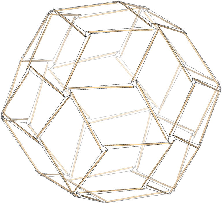
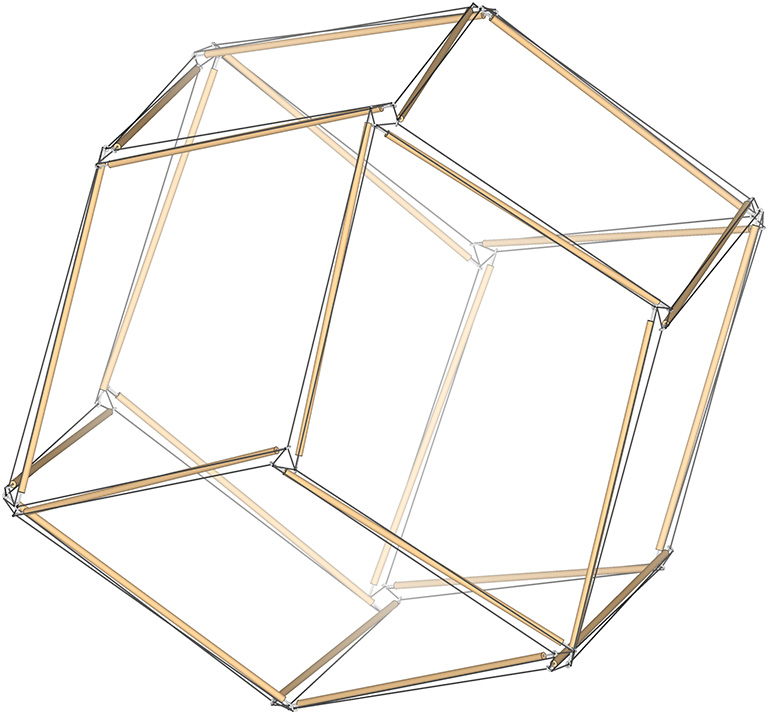
The 24-strut tensegrity sphere is the spherical, or tensor equilibrium phase of the tensegrity rhombic dodecahedron and its dual, the tensegrity vector equilibrium (VE). It also reduces to the double-edge tensegrity octahedron and its dual, the double-edge tensegrity cube.
The 24-strut tensegrity sphere.
The rhombic dodecahedron is the dual of the vector equilibrium (VE).
The rhombic dodecahedron (blue) and its dual, the vector equilibrium or VE (pink). Note that the vertices in one are the faces in the other, and vice versa.
Rectification of either (i.e., the intersection of both) produces a non-uniform rhombicuboctahedron.
Rectification of either the rhombic dodecahedron or the vector equilibrium (left) produces the rhombicuboctahedron (right). Note that the edges of the rhombic dodecahedron and vector equilibrium cross at the vertices of the rhombicuboctahedron.
The 48 edges of a rhombicuboctahedron consist of six intersecting octagons. If we make the six octagons uniform and connect alternate vertices, we produce six squares whose edges align with the distribution of the struts in the 24-strut tensegrity sphere.
The 48 edges of the uniform rhombicuboctahedron describe six intersecting octagons (left). Connecting alternate vertices describes six intersecting squares (right).
Each of the six intersecting squares of the 24-strut tensegrity sphere consists of four struts and the triangular cross section of the valley formed by the tendons connecting each strut-pair to its dangler. The dimensions of this triangular cross-section are illustrated below.
n (number of sides of the polygon) = 4
δ = 180°/n = 45°
S = strut length
d (vertical distance from polygon’s edge to strut) = S×tan(δ/2)/4
d’ (height of the triangle formed by the strut ends and the polygon’s vertex) = d×cos(δ)
h (height of the triangle formed by the strut ends and the midpoint of their dangler strut) = d+d’
gap (distance between strut ends) = S×sin²(δ/2)/2
dip (distance from strut end to midpoint of dangler strut) = S×sin(δ/2)/2
Dimensions of the cross section of the tension valley formed by the four tendons of a strut pair and their dangler in the 24-strut tensegrity sphere.
In its spherical, or equilibrium phase, the dimensions of the cross section of the tension valley created by the tendons reach their maximum. In the polyhedral phases described below, δ approaches to 0°, and both the gap and dip go to zero (0).
In its spherical, or equilibrium phase, the struts are at their maximum distance from the unit edges of the six intersecting squares (left) of the 24-strut tensegrity sphere (right).
Transformation of the 24-Strut Tensegrity Sphere to the Tensegrity Vector Equilibrium (VE)
From the spherical phase, the 24-strut tensegrity sphere is reduced to the tensegrity VE by moving each strut along the long tendon toward the end of its dangler, as illustrated below.
In the transformation from 24-strut tensegrity sphere to the tensegrity VE, each strut end moves along its long tendon to the end of its dangler.
The surface of the 24-strut tensegrity sphere describes eight triangular tendon-loops, six square tendon-loops, and twelve rhombic loops. A face-on view of one of the triangular tendon loops is illustrated below.
24-strut tensegrity in its spherical phase with the view oriented on one of its eight equilateral triangle tendon loops.
In the transition to the VE, the eight triangular tendon loops transform into the VE’s eight triangular faces, the six square tendon loops transform into the VE’s six square faces, and the twelve rhombic loops transform into the VE’s twelve vertices.
24-strut tensegrity vector equilibrium (VE)
24-strut tensegrity transforming between its spherical phase and the tensegrity VE.
Transformation of the 24-Strut Tensegrity Sphere to the Tensegrity Rhombic Dodecahedron
From the spherical phase, the 24-strut tensegrity sphere is reduced to the tensegrity rhombic dodecahedron by moving each strut along the short tendon toward the end of its dangler, as illustrated below.
In the transformation from the 24-strut tensegrity sphere to the tensegrity rhombic dodecahedron, each strut moves along the short tendon to the end of its dangler
The surface of the 24-strut tensegrity sphere describes eight triangular tendon-loops, six square tendon-loops, and twelve rhombic loops. One of the twelve rhombic tendon loops is right-center in the illustration below.
24-strut tensegrity sphere viewed with one of its twelve rhombic tendon loops face-on right of center.
In the transition to the rhombic dodecahedron, the twelve rhombic tendon loops transform into the rhombic dodecahedron’s twelve rhombic faces, the six square tendon loops transform into its six 4-strut vertices, and the eight triangular loops transform into its eight 3-strut vertices.
24-strut rhombic dodecahedron
24-strut tensegrity transforming between its spherical phase and the tensegrity rhombic dodecahedron.
Transformation of the 24-Strut Tensegrity Sphere to the Double-Edged Tensegrity Octahedron
From its spherical phase, the 24-strut tensegrity can be transformed into a double-edge octahedron or a double-edge VE by moving the strut pairs together to either the left or right end of their danglers. That is, one strut moves along the short tendon, while the other moves along the long tendon toward the same end of their dangler.
In the transformation from 24-strut tensegrity sphere to the double-edge tensegrity octahedron or VE, each strut pair moves in the same direction to one end or the other of their dangler.
The surface of the 24-strut tensegrity sphere describes eight triangular tendon-loops, six square tendon-loops, and twelve rhombic tendon-loops. In the illustration below, the six square loops have contracted to the vertices of the double-edge octahedron, while the eight triangular tendon loops have expanded into its eight faces, and the twelve rhombic tendon loops have transformed into its twelve edges.
24-strut double-edge octahedron
24-strut tensegrity transforming between its spherical phase and the double-edge tensegrity octahedron.
Transformation of the 24-Strut Tensegrity Sphere to the Double-Edged Tensegrity Cube
The surface of the 24-strut tensegrity sphere describes eight triangular tendon-loops, six square tendon-loops, and twelve rhombic tendon-loops. In the illustration below, the eight triangular loops have contracted to the vertices of the double-edge cube, while the six square tendon loops have expanded into its eight faces, and the twelve rhombic tendon loops have transformed into its twelve edges.
24-strut double-edge tensegrity cube.
24-strut tensegrity transforming between its spherical phase and the double-edge tensegrity cube.
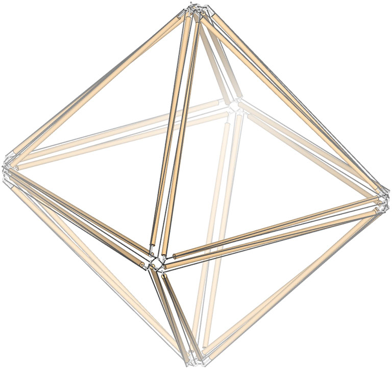
The 12-strut tensegrity sphere is the spherical, or tensor equilibrium phase of the tensegrity cube and its dual, the tensegrity octahedron. It also reduces to the double-edge tensegrity tetrahedron and its dual, which is the same polyhedron but with the vertices and faces transposed.
12-strut tensegrity sphere.
The cube is the dual the regular octahedron.
The cube (blue) and its dual, the regular octahedron (pink). Note that the vertices in one are the faces in the other, and vice versa.
Rectification of either produces the cuboctahedron, i.e, the vector equilibrium or VE.
Rectification of either (or the intersection of both) the cube or the regular octahedron (left) produces the cuboctahedron, i.e. vector equilibrium or VE (right). Note that the edges of the cube and regular octahedron cross at the vertices of the VE.
The 24 edges of the VE describe four intersecting hexagons. Connecting alternate vertices of these hexagons describes four equilateral triangles whose edges align with the distribution of the struts in the 12-strut tensegrity sphere.
The 24 edges of the VE describe four intersecting hexagons (left). Connecting alternate vertices describes four intersecting equilateral triangles (right).
Each of the four intersecting triangles of the 12-strut tensegrity sphere consists of three struts and the triangular cross section of the valley formed by the tendons connecting each strut-pair to its dangler. The dimensions of this triangular cross-section are illustrated below.
n (number of sides of the polygon) = 3
δ = 180°/n = 60°
S = strut length
d (vertical distance from polygon’s edge to strut) = S×tan(δ/2)/4
d’ (height of the triangle formed by the strut ends and the polygon’s vertex) = d×cos(δ)
h (height of the triangle formed by the strut ends and the midpoint of their dangler strut) = d+d’
gap (distance between strut ends) = S×sin²(δ/2)/2
dip (distance from strut end to midpoint of dangler strut) = S×sin(δ/2)/2
Dimensions of the cross section of the tension valley formed by the four tendons of a strut pair and their dangler in the 12-strut tensegrity sphere.
In its spherical, or equilibrium phase, the dimensions of the cross section of the tension valley created by the tendons reach their maximum. In the polyhedral phases described below, δ approaches to 0°, and both the gap and dip go to zero (0).
In its spherical, or equilibrium phase, the struts are at their maximum distance from the unit edges of the four intersecting equilateral triangles (left) of the 12-strut tensegrity sphere (right).
Transformation of the 12-Strut Tensegrity Sphere to the Tensegrity Cube
From the spherical phase, the 12-strut tensegrity sphere is reduced to the tensegrity cube by moving each strut along the short tendon toward the end of its dangler, as illustrated below.
In the transformation from 12-strut tensegrity sphere to tensegrity cube, each strut end moves along the short tendon to the end of its dangler.
The surface of the 12-strut tensegrity sphere describes eight triangular tendon-loops and six square tendon-loops. A face-on view of one of the square tendon loops is illustrated below.
12-strut tensegrity in its spherical phase with the view oriented on one of its six square tendon loops.
In the transition to the cube, the six square tendon loops transform into the cube’s six faces, while the eight triangular loops transform into the cube’s eight vertices.
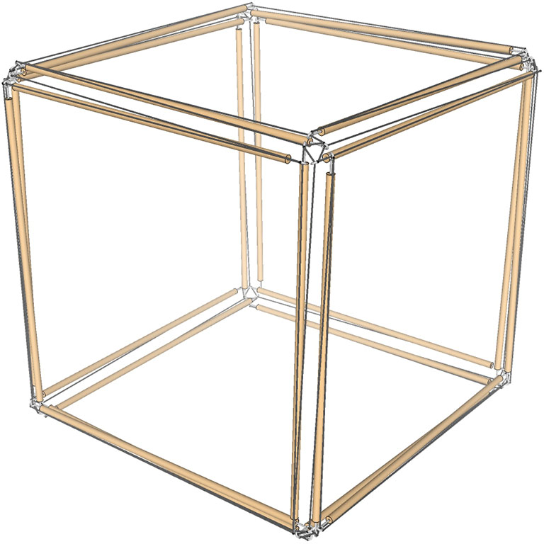
Tensegrity Cube
12-strut tensegrity transforming between its spherical phase and the tensegrity cube.
Transformation of the 12-Strut Tensegrity Sphere to the Tensegrity Octahedron
From the spherical phase, the 12-strut tensegrity sphere is reduced to the tensegrity octahedron by moving each strut along the long tendon toward the end of its dangler, as illustrated below.
In the transformation from 12-strut tensegrity sphere to the tensegrity octahedron, each strut end moves along its long tendon to the end of its dangler.
The surface of the 12-strut tensegrity sphere describes eight triangular tendon-loops and six square tendon-loops. A face-on view of one of the triangular tendon loops is illustrated below.
The 12-strut tensegrity in its spherical phase oriented on one of its eight triangular tendon loops.
The six square loops of the 12-strut tensegrity sphere reduce to form the six vertices of the tensegrity octahedron, while the eight triangular loops expand of form its eight faces.
Tensegrity Octahedron
The 12-strut tensegrity transforming between its spherical phase and the tensegrity octahedron.
The oscillation from the tensor equilibrium (spherical) phase, to the extremes of the cube and octahedron phases, may be stopped at any point and the model will hold its shape. As long as the elasticity and tautness of the tendons is maintained, the models do not show a preference for one state over another.
12-strut tensegrity oscillates smoothly from its spherical phase, between the extremes of its polyhedron phases, all the time holding its shape and showing no preference for one phase over another.
Note that the orientations (clockwise or counter-clockwise) of the triangular and square loops are mutually opposed. That is, if one is oriented clockwise, then the other will necessarily be counter-clockwise. That is, each polyhedron will always be counter the orientation of its dual at the other extreme of the transformation. This, however, does not seem to be the case for double-edged tetrahedron described below.
Transformation of the 12-Strut Sphere to the Double-Edged Tetrahedron
From its spherical phase, the 12-strut tensegrity can be transformed into a double-edged tetrahedron by moving the strut pairs together to either the left or right end of their danglers. That is, one strut moves along the short tendon, while the other moves along the long tendon toward the same end of their dangler.
In the transformation from 12-strut tensegrity sphere to the double-edge tensegrity tetrahedron, each strut pair moves in the same direction to one end or the other of their dangler.
The surface of the 12-strut tensegrity sphere describes eight triangular tendon-loops and six square tendon-loops. A face-on view of one of the triangular tendon loops is illustrated below. On the left, the triangular loop is contracting to a vertex, while on the right, the triangular loop is expanding to a face. In both cases, the six square tendon loops are transformed into the six edges of the double-edge tetrahedron.
The 12-strut tensegrity approximately midway between its spherical phase and the double-edge tensegrity tetrahedron. Four of the eight triangular tendon loops transform into vertices (left), while the other four transform into faces (right).
Note that both transformations (moving the strut pairs to either end of their danglers) produce the same double-edge tetrahedron. This is consistent with the fact that the tetrahedron is its own dual; the number of faces (4) is the same as the number of vertices (4), so transposing the two has no effect. However, with the other duals, if one’s vertices are oriented clockwise, the other’s are oriented counter-clockwise. With the double-edge tensegrity tetrahedron, the vertices are neither and both: three struts converge at the vertex oriented in one direction, and the other three come together oriented in the opposite direction, one effectively neutralizing the other.
The double-edge tetrahedron and, presumably, all the double-edge tensegrity polyhedra are, by the above reasoning, neutral counterparts to their polarized, single-edge counterparts. This may have intriguing implications for their relevance as models of quantum, chemical, and other physical interactions and open doors for theoretical exploration and research.
The two transformations, moving the strut pairs to one end or the other of their danglers, produces the same double edge tetrahedron.
As with the transformations described above, the oscillations between the two double-edged tetrahedra may be stopped at any point in the process. The models do not some seem to prefer any one state over another, and will hold their shape in the transitional stages as well as at the extremes.
The 12-strut tensegrity transforming between two orientations of the double-edge tetrahedron via its spherical phase.