I’ve used the equations described in this topic to calculate the strut and tendon lengths of the tensegrity sphere models I describe in Model Making. They are slightly modified from those published by Hugh Kenner in his book, Geodesic Math and How To Use It (1976, 2003). See also: Tensegrity.
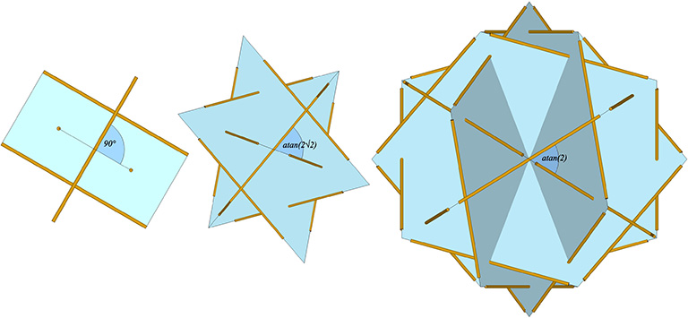
After some rather clever reasoning, Kenner concluded that all of the dimensions of the tensegrity spheres could be derived from just two quantities: the number of sides (n) in their great circle (or lesser circle) planes, and the angle (µ) at which they cross. The following illustration shows the three primary tensegrity spheres, i.e., the spherical phases of the tensegrity tetrahedron, octahedron, and icosahedron:
- the six-strut tensegrity sphere with three great circles planes of two struts (n=2), each crossing at µ=90°;
- the twelve-strut tensegrity sphere with four great-circle planes of three struts (n=3), each crossing at µ=atan(2√2) ≈ 70.530°; and,
- the thirty-strut tensegrity sphere with six great circle planes of five struts (n=5), each crossing at µ=atan(2) ≈ 60.435°.
The intersection of the great-circle and lesser-circle planes can be broken down to two struts and a dangler, as in the following illustration.
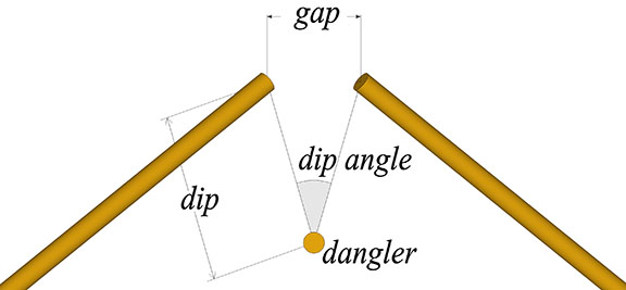
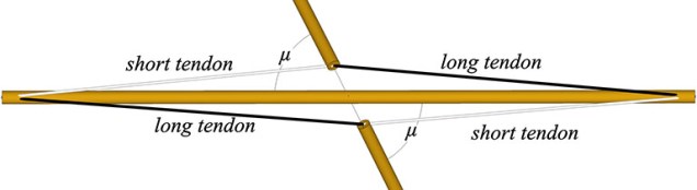
The dangler strut’s great circle crosses the great circle of the other two struts at an angle, µ. If this angle is less than 90° (as is the case for all but the six-strut tensegrity sphere), the tension elements will consist of a long and a short tendon, as shown in the following illustration.
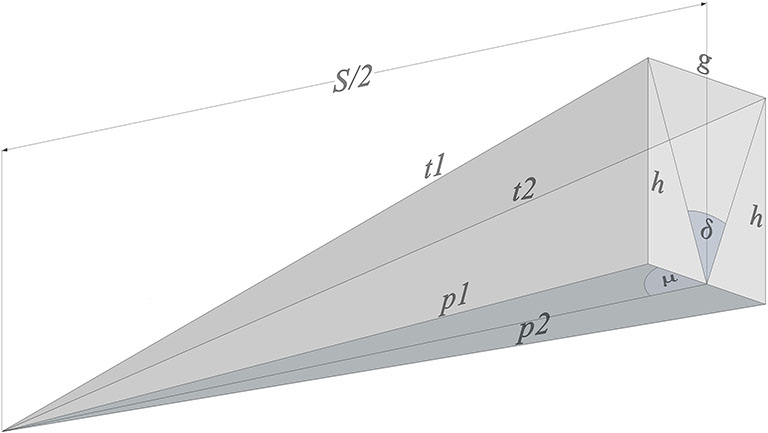
The next illustration shows the relationships between all the parameters that go into calculating the circumsphere radius, strut length, and tendon lengths of the tensegrity spheres:
- S = strut length;
- r = the circumsphere radius, from sphere center to each of the strut endpoints;
- dangler = the strut bisected by the great circle plane of two struts;
- μ = the angle the great circle plane of the dangler makes with the great circle plane of the two struts;
- d = dip, i.e., the distance between each strut’s endpoint and the midpoint of its dangler;
- δ = the dip angle, i.e., the angle between the dangler’s midpoint and the two strut endpoints;
- g = the gap, i.e. the linear distance between the two strut endpoints;
- h = the vertical distance between a strut’s endpoint and the horizontal plane of its dangler;
- t1 and t2 = the length of the short and long tendons, respectively;
- p1 and p2 = the base of the right angle made with h, and with t1 or t2 as its hypotenuse, respectively.
The Equations
- S = strut length
- dip angle (δ) = 180°/n
- gap (g) = S×sin²(δ/2)
- dip (d) = S×sin(δ/2)/2 = √g/2
- height (h) = √((g–g²)/4)
- p1 = √[(S/2)²+(g/2)²+((S/2)×g×cos(µ))]
- p2 = √[(S/2)²+(g/2)²- ((S/2)×g×cos(µ))]
- short tendon (t1) = √(h²+p1²)
- long tendon (t2) = √(h²+p2²)
- circumsphere radius (r) = √((1+3g)/16g)
