Geodesic polyhedra are convex polyhedra consisting of triangles, and include the spherical polyhedra generated by subdividing the faces of a tetrahedron, octahedron, or icosahedron into smaller triangles and projecting their crossings out to the underlying polyhedron’s circumsphere radius. Those based on the icosahedron are related to but not necessarily aligned with the 31 great circles of the icosahedron from which their name seems to have originated. The name “geodesic” refers to Fuller’s early conviction that only a triangular latticework of geodesic lines would serve to distribute local stresses evenly throughout the system he patented under the name “Geodesic Dome” in 1954. As the domes evolved into the systems of mostly partial great circles and lesser circles described here, the term “geodesic polyhedra” preserved the memory of that earlier conviction.
Geodesic polyhedra are defined by the equilateral triangles of the primary face (i.e., the face of the underlying tetrahedron, octahedron, or icosahedron) laid out on a 60° grid so that their vertices always align with grid crossings. This produces three classes of tiling or tessellation. The edges of the primary triangular face in Class 1 are parallel to the grid lines. The edges in Class 2 are perpendicular to the grid lines. Those in Class 3 are neither parallel nor perpendicular to the grid lines.
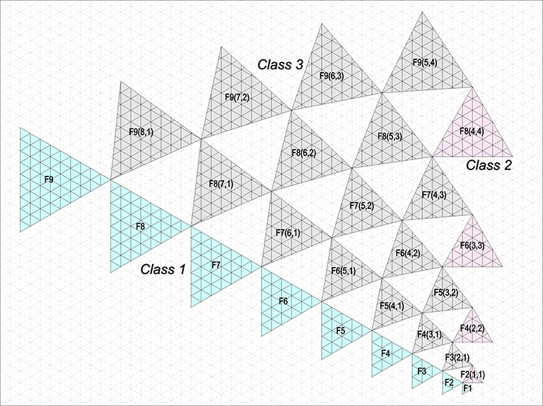
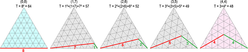
The frequency of each class is given by two numbers (b,c) representing the number of triangular modules along the grid lines connecting adjacent vertices. The general formula for the area, or the number of triangular modules that subdivide the primary face, is given by:
Area (T) = b² + c² + (b×c)
For Class 1, b is the edge length of the primary face; so, c is always 0 and the formula reduces to b². For Class 2, b = c, so the formula can be reduced to 3b².
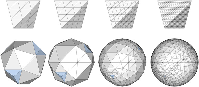
Class 1 Geodesics
Class 1 geodesics subdivide the primary face with lines parallel to the edges.
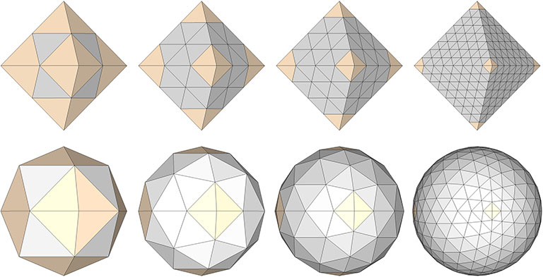
Class 2 Geodesics
Class 2 geodesics subdivide the primary face with lines perpendicular to the edges.
Class 3 Geodesics
Class 3 geodesics subdivide the face with lines that are askew to the edges, neither parallel no perpendicular.

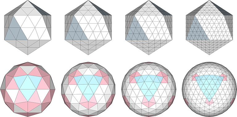
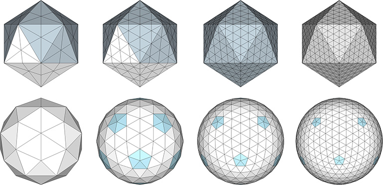
All of the geodesic polyhedra above have as their base the regular icosahedron. Being the most spherical, the icosahedron generates the most uniform tessellations. But the geodesic polyhedra may also be generated using the tetrahedron as their base, as in the following examples:
And they may also be generated using the octahedron as their base, as in these examples:
The spherical tensegrities, whether based on the tetrahedron, octahedron, or icosahedron, have the shape of Goldberg polyhedra, the duals of geodesic polyhedra. Fuller held that all of his geodesic domes were, structurally, tensegrities. But then, any self-supporting structure can be described as a tensegrity. That is, all structural arrangements of vectors can be described as islands of compression in a continuous web of tension. Perhaps Fuller meant that his calculations were done on the spherical tensegrities, i.e., the tensor equilibrium phases of the tensegrity forms of the geodesic polyhedra. (See: Tensegrity, and; Tensegrity Equilibrium and Vector Equilibrium.) Many of Fuller’s domes do, in fact, have the appearance of Goldberg polyhedra. Fuller’s geodesic structures may be most accurately described as tensegrity composites incorporating both their spherical and polyhedron states.

An alternate construction of the 2F Class 1 geodesic polyhedron is achieved by reducing the the 120-strut tensegrity sphere to its polyhedron phase.
Composite tensegrities, incorporating the spherical (Goldberg) and polyhedron (geodesic) phases of two or more frequencies may be possible without one interfering with the other. These may be easier to construct and would no doubt have incredible strength.
