The 120-strut tensegrity model described earlier uses the “zigzag,” rather than the “circuit” pattern that was used for the 6-, 12-, and 30-strut tensegrity spheres. The terms refer to the paths the tendons take between strut ends.
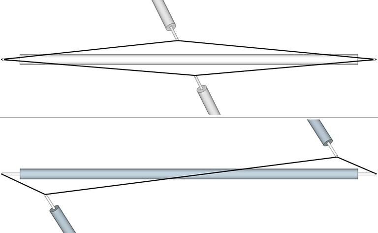
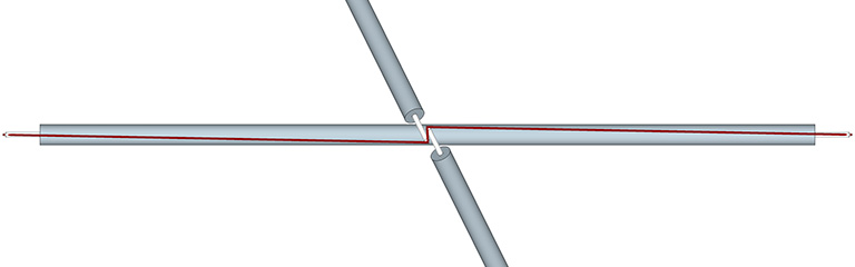
The zigzag pattern, though not the ideal pattern for any “true” tensegrity structure, does make modeling the polyhedral tensegrities a bit simpler. It is less practical, however, for modeling the spherical tensegrities; as the strut ends move closer together, the pattern introduces tension that works against the the integrity of the structure, as I’ve tried to show below.

We can reduce this negative tension by increasing the length of the struts until they overlap. This reduces and redirects the negative tension and allows the structure to approach, but not fully reach, the spherical phase. This approach was used in the 120-strut tensegrity model described earlier, and is a common strategy for modeling the more complex tensegrities.
In the following, I use the zigzag pattern to construct models of the tensegrity tetrahedron, octahedron, and icosahedron.
Materials:
- 1/4″ wooden doweling.
- 3/64″ inch braided polyester/nylon cord.
Procedure:
- Cut the 1/4″ doweling into the lengths specified for the specific model.
- Make two perpendicular cuts, about 1 mm wide and 1/4″ deep, into the ends of each strut so that the cuts at both ends align. The cuts should slightly thinner than the cord being used for the tendons. Any coping saw, jigsaw, or band saw should work.
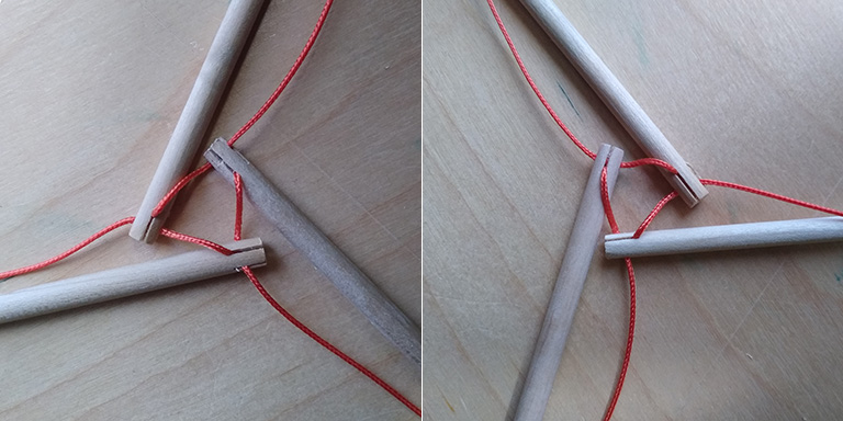
- Pull the braided cord through a slot at one end of each strut, leaving a short length from the end of the cord dangling.
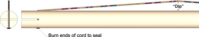
- Hold the strut with the dangling cord briefly over a candle (or other source of flame) and pull away just as the dangling end of the cord begins to melt, then carefully flatten the melted cord (it will be hot!) against the strut to form a seal that will prevent the cord from being pulled out of the slot.
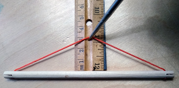
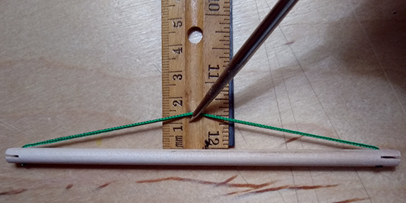
- Pull the cord along the length of the strut, then down and through the slot at the opposite end until taut.
- With the cord pulled tight against the strut, grasp the cord halfway along its length and pull away from the strut to create just enough slack as the “dip” specified for the of the specific model.
- Cut the cord and seal the end as before.
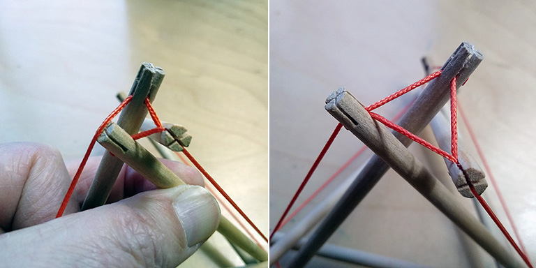
Assemble by sliding the braided cord of each dangler into the slots of its connecting struts. Friction alone should hold the struts in place until the structure is fully assembled.
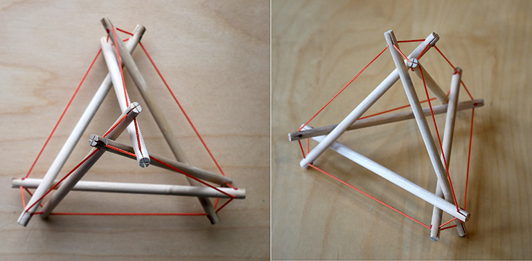
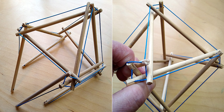
6-Strut Tensegrity Tetrahedron
This produces a fairly compact tensegrity tetrahedron that stands about 5 inches (12.7 cm) high.
Make six, 6-inch (15.25 cm) struts as described above with a dip of about 3 cm.
Note: A smaller dip will force the strut ends together and make for a more polyhedral shape, but the model will be more difficult to assemble.
Step 1. Link three struts into a clockwise, or counter-clockwise triangle. This forms one of the four triangular vertices of the tetrahedron.
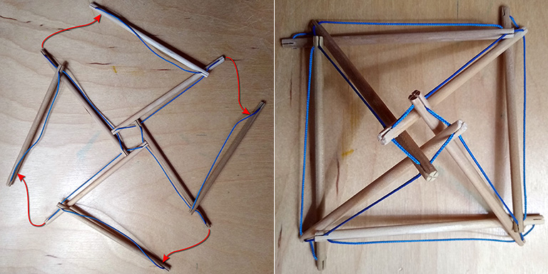
Step 2. Add three additional struts and connect as illustrated to form a loosely-structured tetrahedron.

Step 3. Turn the assembly over and connect the remaining strut-ends to form three additional triangular vertices, making sure to connect them in the same direction (clockwise or counter-clockwise) as the one you assembled in Step 1.
Step 4. Adjust the structural tension by widening (to increase tension) or narrowing (to decrease tension) each of the triangles that form the four vertices of the tetrahedron.
12-Strut Tensegrity Octahedron
This produces a tensegrity octahedron approximately 7.5 inches (19 cm) in diameter.

Make twelve, 6-inch (15.25 cm) struts as described above with a dip of about 2 cm.
Note: A smaller dip will force the strut ends together and make for a more polyhedral shape, but the model will be more difficult to assemble.

Step 1. Link four struts into a clockwise, or counter-clockwise square. This forms one of the six vertices of the octahedron.

Step 2. Add four additional struts and connect as illustrated to form a pyramid shape, i.e., a four-sided prism with a square base.
Step 3. To the pyramid, attach four additional struts as illustrated. Note that after making all the connections shown, you will have made five additional square vertices, all assembled in the same direction (clockwise or counter-clockwise) as one assembled in Step 1.

Step 4. Turn the assembly over and connect the remaining strut-ends to form the final square vertex, making sure to connect them in the same direction (clockwise or counter-clockwise) as the others.
Step 5. Adjust the structural tension by widening (to increase tension) or narrowing (to decrease tension) each of the squares that form the six vertices of the octahedron.
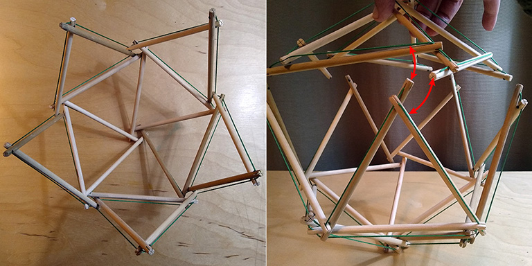
30-Strut Tensegrity Icosahedron
This produces a tensegrity icosahedron approximately 9 inches (about 23 cm) in diameter.

Make thirty, 6-inch (15.25 cm) struts as described above with a dip of about 1.25 cm.
Note: A smaller dip will force the strut ends together and make for a more polyhedral shape, but the model will be more difficult to assemble.
Step 1. Link five struts into a clockwise, or counter-clockwise pentagon. This forms one of the twelve vertices of the icosahedron.

Step 2. Add five additional struts and connect as illustrated to form a pentagonal prism.

Step 3. Make a second pentagonal prism identical with the first. This will be used in the final step.
Step 4. To the first pentagonal prism, attach ten additional struts and connect as illustrated. Note that after making all the connections shown, you will have made five additional pentagonal vertices, all assembled in the same direction (clockwise or counter-clockwise) as one assembled in Step 1.

Step 5. Turn the assembly over and attach to the second pentagonal prism you assembled in Step 3.
Step 6. Adjust the structural tension by widening (to increase tension) or narrowing (to decrease tension) each of the twelve pentagonal vertices of the icosahedron.
