“Synergetics is a book about models: humanly conceptual models; lucidly conceptual models; primitively simple models; rationally inter-transforming models; and the primitively simple numbers uniquely and holistically identifying those models and their inter-transformative, generalized and special case, number-value accountings. […] How we think is epistemology, and epistemology is modelable; which is to say that knowledge organizes itself geometrically, i.e., with models.”
—R. Buckminster Fuller, Synergetics, 900.21
I’ve added a second page for this topic. See also: More Model Making.
For constructing the physical models essential to both an intuitive and a rational understanding of Fuller’s geometry, I prefer the following materials and methods. The materials are relatively inexpensive to purchase in bulk, and the methods are relatively simple.
Though perhaps a bit tedious, building these models is worth the trouble. Not only is the physical model an essential tool for grasping the geometric and structural principles involved; but in our increasingly abstract and mediated realities, there is nothing so satisfying as a model that states its principles in pure, unambiguous terms, and asserts its truth by the simple fact of its undeniable physical existence.
Note: I’ve uploaded most of these models as Sketchup files to 3D Warehouse. To view and/or download them, go to the 3D Warehouse website at https://3dwarehouse.sketchup.com/. To see everything I’ve added so far, use the search term, “geometryofthinking.”
This page presently includes instructions for building the following models:
- Polyhedra
- Vector Equilibrium (VE)
- Isotropic Vector Matrix
- The Jitterbug
- Geodesic Polyhedra
- Tetrahelix
- A Curious Helical Structure
- Tensegrity
Polyhedra
“Any polygon with more than three sides is unstable. Only the triangle is inherently stable. Any polyhedron bounded by polygonal faces with more than three sides is unstable. Only polyhedra bounded by triangular faces are inherently stable. By structure, we mean a self-stabilizing pattern. The triangle is the only self- stabilizing polygon. By structure, we mean omnitriangulated. The triangle is the only structure. Unless it is self-regeneratively stabilized, it is not a structure.”
—R. Buckminster Fuller, Synergetics, 609.01–610.02
The flexible silicone connectors described below allow you to easily determine whether a given shape meets Fuller’s definition of “structure.” The triangle is the only self-stabilizing pattern in two dimensions, i.e., the only rigid polygon. But in three dimensions, the “omni-triangulation” that Fuller insists upon isn’t always obvious. This is especially true in the tensegrity models I describe further down.
Tools needed:
- Needle-nose pliers
- Wire cutter
Parts:
- Plastic cake pop sticks (6″ x 5/32″, 152mm x 4mm)
- Stainless steel wire (28 to 22 gauge, 0.37mm to 0.7mm))
- Flexible silicone rubber tubing (3mm ID, 5mm OD)
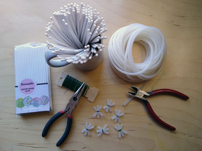
Procedure:
- Using a wire cutter, knife, or scissors, cut one-inch lengths (2.5 cm) from the silicone tubing.
- Cut the wire into manageable lengths (about 2.5 inches, or 6 cm).
- Bundle together three lengths of the silicone tubing by wrapping two loops wire around their middle, leaving equal lengths of wire from each end free.
- Then, holding one end of the wire in one hand, grasp the other with the needle nose pliers and pull the wire tight, squeezing the bundle together to form star-like connectors as shown in the above photo. (This may take some practice.)
- Give the wire a twist and snip off the ends.
Assemble the polyhedron by inserting the sticks into the open ends of the connectors. For the vector equilibrium (VE) you’ll need to bundle together two connectors, i.e. two bundles of three, for the twelve sticks that serve as its radials.
Regular Polyhedra
Fuller states that all structural phenomena are accounted for in terms of the tetrahedron, octahedron, vector equilibrium, and icosahedron. The regular tetrahedron, octahedron, and icosahedron, are the only polyhedra that are triangulated (all sides are triangles), regular (all sides are of equal length, and all faces are identical polygons), symmetrical (rotational symmetry, specifically), and rigid (i.e., when constructed with universally flexible connectors at their vertices, they will hold their shape under load).
The claim that these account for all structural phenomena is simply an acknowledgement that no other polyhedron meets all these conditions, at least in three dimensions.
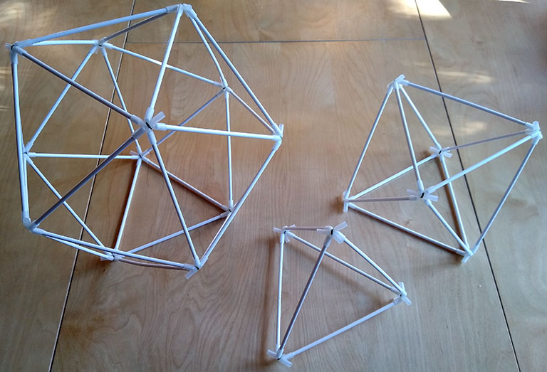
- The regular tetrahedron requires six struts and four connectors, and every vertex joins three edges. To construct, join three struts at each of its four vertices.
- The regular octahedron requires twelve struts and six connectors, and every vertex joins four edges. To construct, join four struts at each of its six vertices.
- The regular icosahedron requires thirty struts and twelve connectors, and every vertex joins five edges. To construct, join five struts at each of its twelve vertices.
Vector Equilibrium (VE)
The vector equilibrium (or “VE”) is the simplest model of the isotropic vector matrix, what Fuller called nature’s coordinate system. Every vertex of the isotropic vector matrix joins twelve vectors; and the same number of unit-radius spheres can be close-packed around a common nucleus. The VE might be classified as a regular polyhedron if we regard its six square “faces” as the base edges of the four equilateral triangles that share a common vertex at the VE’s center.
In the following model, the vectors are represented by the cake-pop sticks (struts), and the sphere centers by the connectors at the vertices.
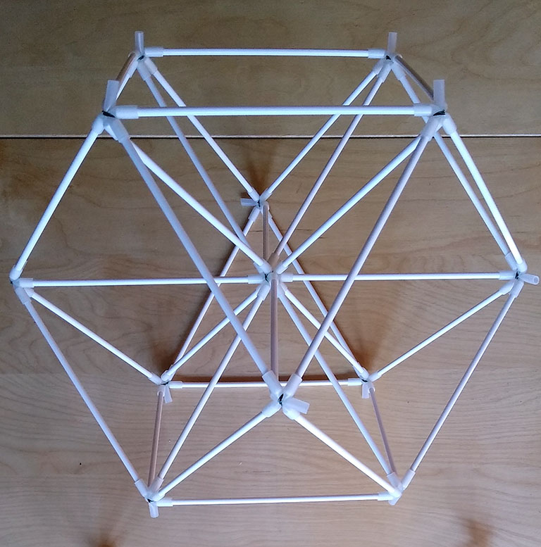
The model requires 24 struts and twelve connectors to define the six square faces and eight triangular faces of the cuboctahedron. An additional twelve struts connecting the vertices with the center stabilize the cuboctahedron in what Fuller called “vector equilibrium.”
To construct, join four struts at each of its twelve vertices. Think of it as joining six squares, or eight triangles, each sharing a single vertex, and arranged around a common center. Bundle two connectors together for the common vertex at which the twelve radial struts converge. In the final model, each external vertex will join five struts—four edge struts, and one radial strut.
Isotropic Vector Matrix
Fuller called the isotropic vector matrix nature’s coordinate system, a system of unit vectors all meeting at 60°, as opposed to the conventional coordinate system of 90° angles which he felt was responsible for so much unnecessary complexity in science and mathematics.
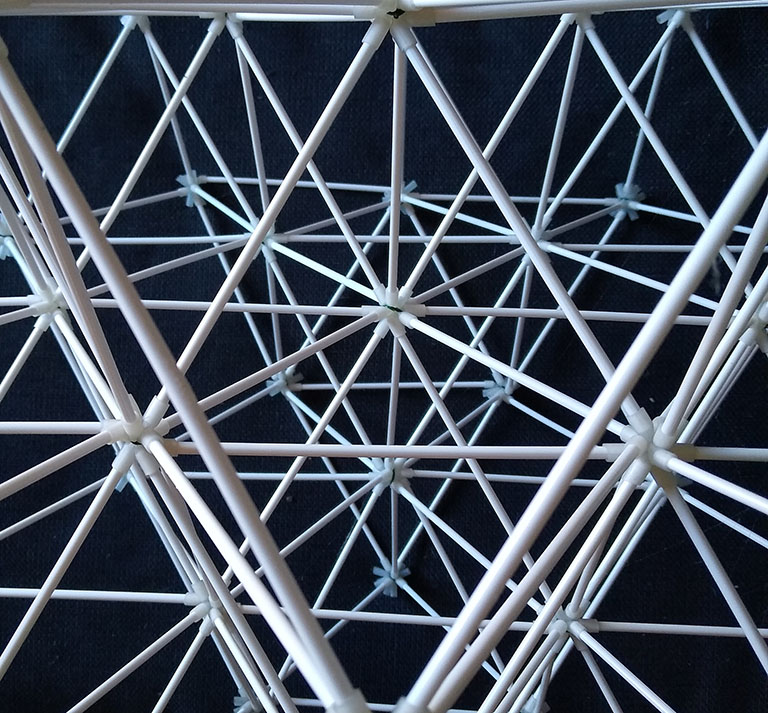
The model can be thought of as a matrix of VEs, each sharing a common (square) face, or as a matrix of octahedra, each sharing a common edge, or as a matrix of tetrahedra, each sharing a common vertex. To construct, you’ll need to bundle together pairs of as many connectors as the scale of your construction requires. All internal connections will have twelve struts joined at a common vertex.
The above illustration is of a portion of a two-frequency VE, i.e., a VE in which each edge consists of two struts, and in which each face has been subdivided by four. This model will require 55 doubled-up connectors and 378 struts.
Jitterbug
For more information on the jitterbug transformation and how it relates to the rest of Fuller’s geometry, see my post titled, Jitterbug.
Begin with a either a VE and remove the twelve radials, or with a regular icosahedron and remove three opposing pairs of edges (six total).
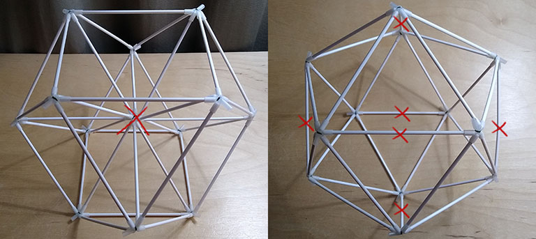
This leaves a floppy cuboctahedron with six square faces and eight triangular faces which can be collapsed into a double-bonded octahedron…
(Click on image to view animation in new tab.)
…or, with an added twist, will collapse into a triangle which can be folded into a quadruple-bonded tetrahedron.
4F Class 1 Geodesic Polyhedron with Icosahedra Symmetry
For more information on the geodesic polyhedra, see my post titled, Geodesics.
I actually haven’t had the patience to build this, but if my calculations are correct, a model correctly assembled with the strut lengths specified below should produce a 4F Class 1 geodesic sphere about 16 inches in diameter.
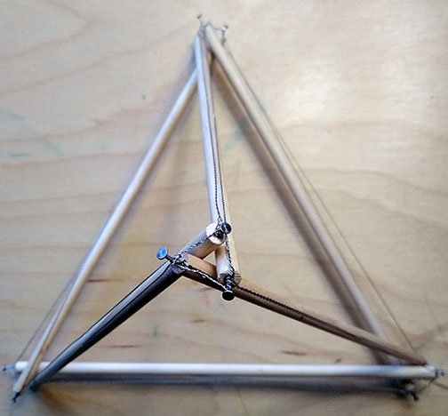
Tetrahelix
The tetrahelix is a linear chain of face-bonded tetrahedra. The helical cycle appears to complete one 360° cycle every 30 tetrahedra, but careful measurement shows a deficit of about 5.690553°. This irrationality permits what may be an infinite number of possible configurations, which led Fuller to speculate on its relation to the DNA molecule and and the unfathomable number of unique proteins it makes possible.
A Curious Helical Structure
I’m intrigued by this helical structure. It doesn’t have a name, as far as I know. Unlike the tetrahelix, whose helical cycle is incommensurate with its component tetrahedra, my analysis shows a twist of exactly six degrees between the top and bottom triangles of each component; so, 60 components stacked one on top of the other would complete a full cycle of 360°. I wrote about this in a topic I posted a while back. See: A Curious Helical Structure.
(Click on image to view animation in new tab.)
To construct the base component of the helix, begin with with a tetrahedron whose base is lying flat the work surface, then face-bond one tetrahedron to each of its three exposed faces. Attach two additional struts to each of the base vertices (those in contact with your work surface) and connect one to each of the three points of the face-bonded tetrahedra, and join the remaining strut ends with three additional struts to from the top triangle. This “top” triangle will be rotated 6° in relation to the “base” triangle. Construct additional components and stack them to form the helix.
Tensegrity Structures
For more information on tensegrity and how it relates to the rest of Fuller’s geometry, see my topic titled, Tensegrity.
The following terminology is borrowed from Hugh Kenner’s book, Geodesic Math and How To Use It, and the parameters they represent were used in my calculations for the tensegrity models.
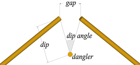
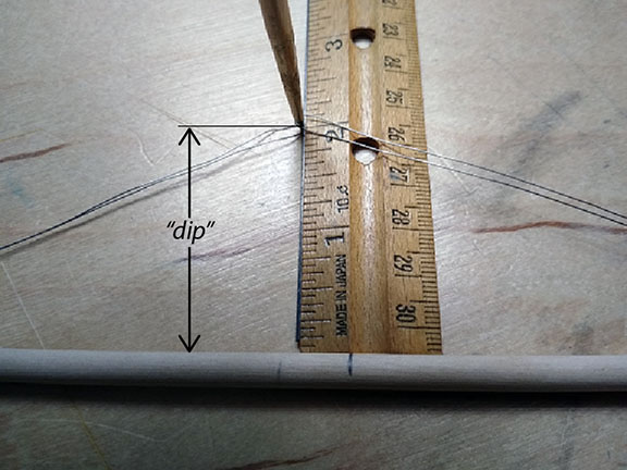
- The gap is the linear distance between the ends of two adjacent struts, and
- the dangler is the strut that passes between them.
- The dip is the distance from either endpoint to the midpoint of the dangler, and
- lines connecting the midpoint of the dangler with the endpoints of the struts spanning the gap define the dip angle.
In the twelve- and thirty-strut tensegrity models, the connections between end points require both a long tendon and a short tendon. One of each is attached to both ends of every strut.
Tools:
- Needle-nose pliers
- Wire cutters
- Wire jig (described below)
Parts:
- Wooden dowel rods (3/16″, 5mm)
- Stainless steel wire (28 gauge, 0.37mm)
- Small box nails
For the three tensegrity models described below, cut the necessary number of dowels into 9-inch (23 cm) lengths and drive a box nail into each of their ends to anchor the tendons. For the twelve- and thirty-strut tensegrities, I find it helpful to color code the struts and to number their ends. For example, the twelve-strut tensegrity has four great-circle groups of three struts each. Each group of struts would be painted a different color (e.g., red, blue, green and black) with their ends labeled 1 through 6.
Measure out a loop of 28 gauge wire to the specified tendon length. Leave an extra inch or so for twisting onto the strut. To ensure consistent and accurate tendon lengths, I use a jig made from a cheap wooden ruler mounted on a base to elevate it off the work surface. I then use small wood screws or brads to wrap the wire around (see illustration below).
Fix two tendon loops to the ends of each strut. If the model uses long and short tendons, attach one of each to both ends.
Check for proper tendon lengths by measuring the “dip” (see illustration).
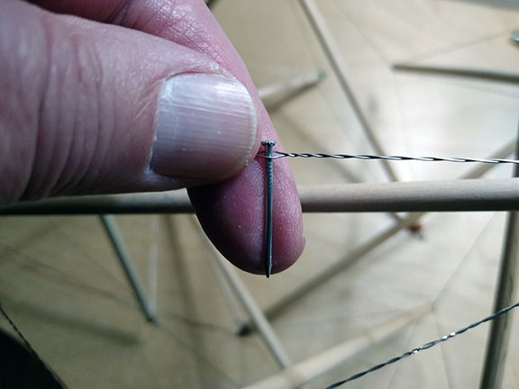
Assemble the model using the net diagram I’ve included as a guide. And finally, adjust tension in the wire by inserting a small nail or toothpick between the two strands of wire and twisting until the desired tension is achieved.
Tensegrity Prisms
Coming soon.
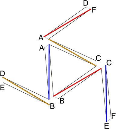
Six-Strut Tensegrity Sphere
For information on calculating the strut and tendon lengths for spherical tensegrities other than those show here, see my topic, Tensegrity Sphere Equations.
The six-strut tensegrity sphere is the spherical, or tensor-equilibrium phase of the regular tetrahedron. (See: Tensegrity Equilibrium and Vector Equilibrium; and Jessen Orthogonal Icosahedron and Tensor Equilibrium.) The overall shape it describes is identical with the Jessen Orthogonal Icosahedron.
- Six 9″ struts from 1/4″ dowel
- Tendon length: 143mm (5 5/8″)
- Dip: 3 1/8″
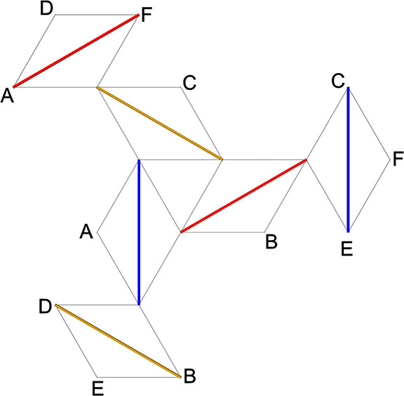
By adjusting the tendon lengths, you can use the same net diagram as above to construct the tensegrity tetrahedron.
The following diagram is for a tensegrity tetrahedron with tendon lengths of 15 mm and 225 mm.
12-Strut Tensegrity Sphere
The twelve-strut tensegrity sphere is the spherical, or tensor equilibrium phase of the regular octahedron. The overall shape it describes is similar to, but not identical with the cuboctahedron and VE.
(Click on image to view animation in new tab.)
- Twelve 9″ struts from 1/4″ dowel
- Tendon lengths: 140mm and 118mm (5 9/16″, 4 3/4″)
- Dip: 2 1/4″
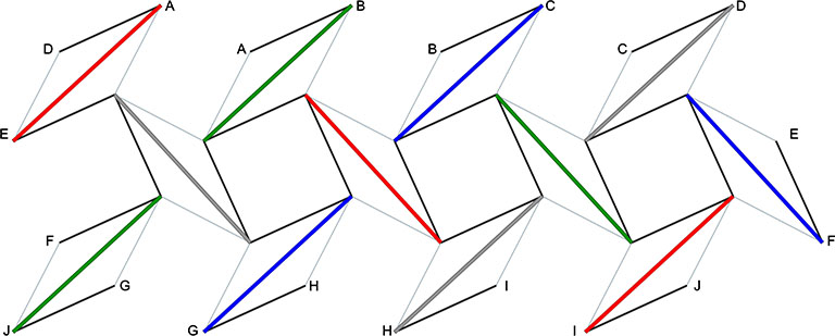
By adjusting the tendon lengths, you can use the same net diagram as above to construct the tensegrity octahedron.
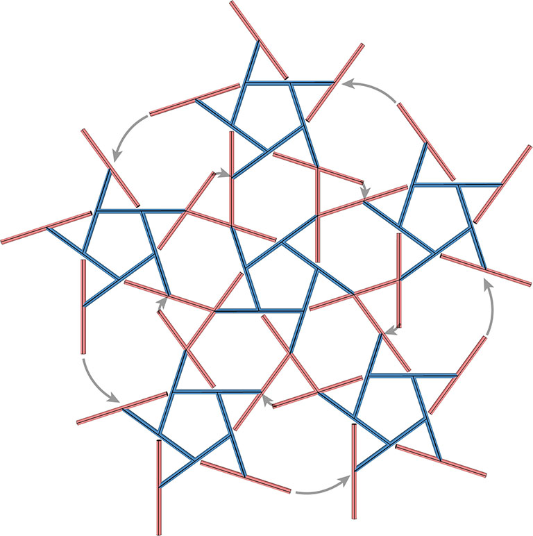
30-Strut Tensegrity Sphere
The 30-strut tensegrity sphere is the spherical, or tensor equilibrium phase of the regular icosahedron. Its overall shape is similar to, but not identical with the icosidodecahedron.
(Click on image to view animation in new tab.)
- 30 9″ struts from 1/4″ dowel
- Tendon lengths: 118mm, 127mm (4 5/8″, 5″)
- Dip: 1 3/8″
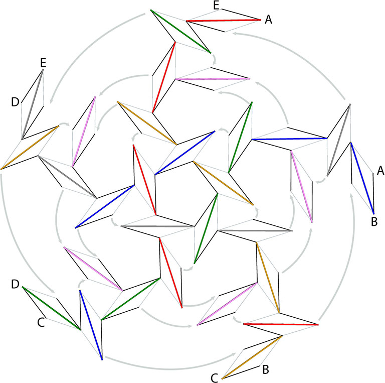
By adjusting the tendon lengths, you can use the same net diagram as above to construct the tensegrity icosahedron.
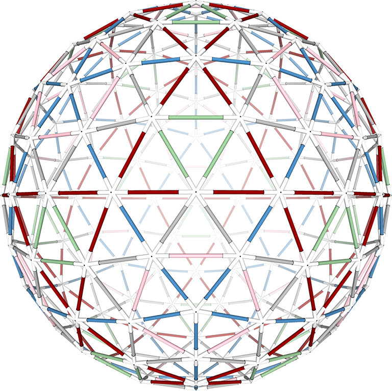
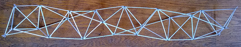
120-Strut Tensegrity Sphere
Fuller said that all of his geodesic domes were engineered as tensegrity structures. Their only difference with true tensegrities were the redundancies that were added to please the aesthetic sensibilities of his clients and to comply with building codes.
This model, I think, clearly demonstrates Fuller’s claim. The diameter of the 1/4″ dowels that were used exceeds the dip between the strut ends and their danglers, and the gap and dip-angle are so slight that the separation of the tension and compression elements has nearly disappeared. If we replaced the tendons with star-hubs, and added radial struts to the pentagons and hexagons in this model (which would do little or nothing to increase the structural strength or rigidity of the structure, and may in fact weaken it) we would have a 4F Class 1 geodesic icosahedron. (See also: Geodesics.)
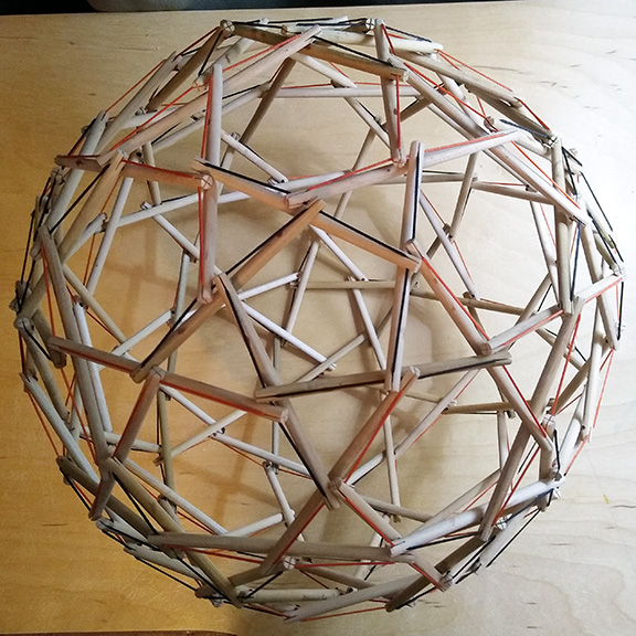
Materials used:
- 1/4″ wooden dowel
- 3/64″ inch braided polyester/nylon cord.
For an approximately 16″ diameter sphere:
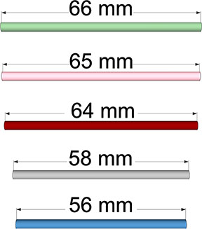
- Cut 1/4″ dowel into 60 lengths of 118 mm, and 60 lengths of 124 mm (4-5/8″ and 4-7/8″), for a total of 120 struts.
- Make two perpendicular cuts, about 1 mm wide and 1/4″ deep, into the ends of each strut so that the cuts at both ends align. The cut should slightly thinner than the cord being used for the tendons.
- For each strut, cut a length of thin braided polyester cord about an inch longer that the struts, and press each end of the cord into parallel slots at each end of the strut. Pull the cord into the slots so that only about 3/16″ inch of give remains (see illustration below). Burn the ends of the cord to seal them into the slots.
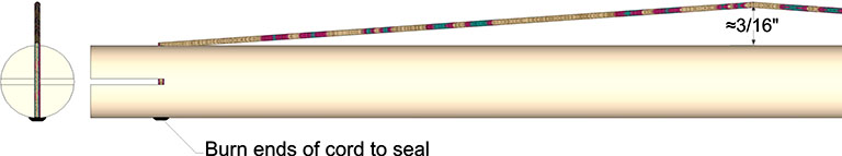
Assemble by sliding the braided cord of each dangler into the slots of its connecting struts. Friction alone should hold the struts in place until the structure is fully assembled. The following partial net diagram should get you far enough to complete the sphere on your own.
This tensegrity sphere reduces to its polyhedral phase as a 2F Class 1 geodesic polyhedron with icosahedron symmetry.
